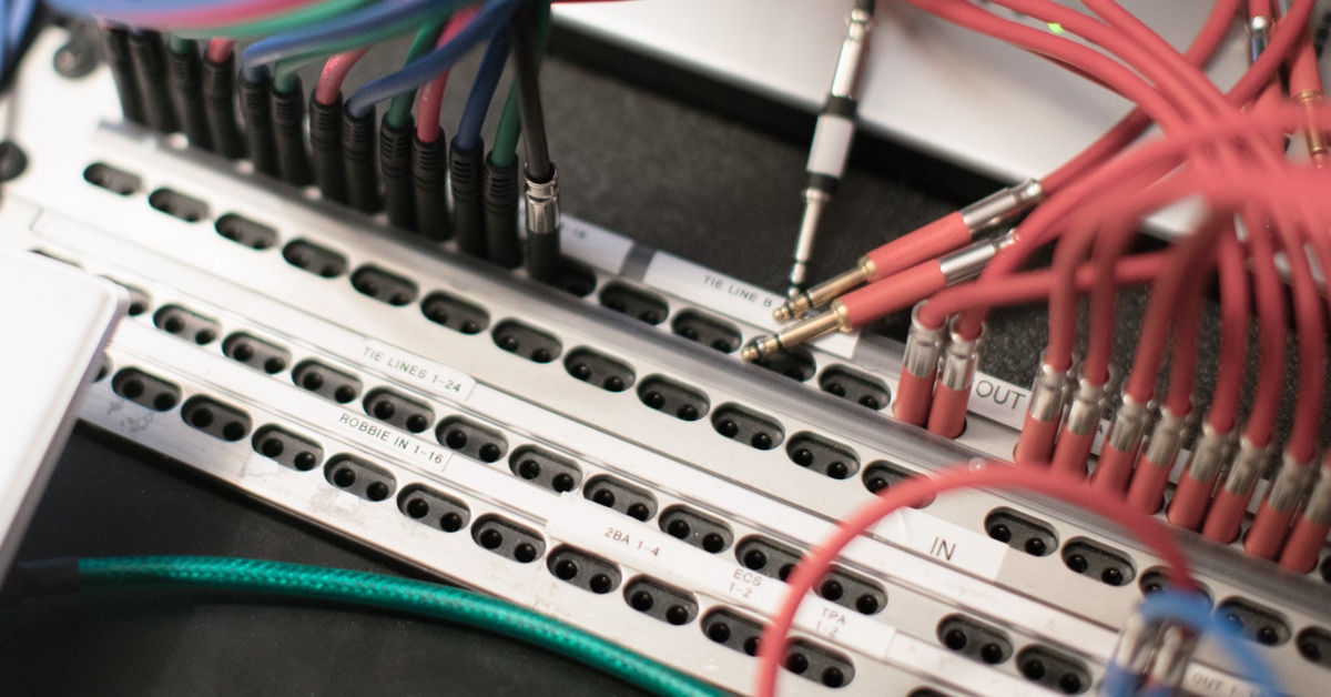
A patch bay enables you to change the signal flow among the devices in your studio without having to crawl behind all your gear and unplug/replug your cables. In addition to eliminating that hassle, patch bays save wear and tear on the jacks of your equipment. Audio patch bays are switchboards for rerouting audio signals; there are also MIDI patch bays for — you guessed it — rerouting MIDI signals.
An audio patch bay has a front panel which contains rows of input and output jacks. On rack-mountable patch bays used in recording studios, there are typically two rows of jacks on the rear panel and two rows of jacks on the front panel. Devices such as mixers, external processors and preamps can be plugged into the patch bay.
Patch bay jack sizes include 1/4" (balanced TRS or unbalanced TS) and TT (Tiny Telephone, used in some commercial studios to save space).
Patch bay jacks are arranged in vertical pairs. A jack on the upper row of the rear of the patch bay receives a signal from the output of a device. The jack immediately below it, on the bottom row of the rear of the patch bay, sends the signal to the input of a device.
A pair of patch bay jacks can be normalled, half-normalled, or de-normalled.
Different types of Patch Bay Configurations
Parallel

In this mode, all terminals of one module are interconnected. This is used to split up and send one audio signal (for example an aux send) to several destinations (such as effects processors).
Half-Normalled

In this mode, the contacts of the two jacks on the rear are interconnected. When you insert a plug into the upper front jack, the signal routed through the rear path is not interrupted. Only when the lower front jack is used will the rear panel route be split up, so that the two upper and the two lower jacks are connected to one another. This configuration is called "input break" and is used mainly for insert paths. You can easily patch the signal from a mixing console channel at the patch bay without interrupting the signal flow in the channel.
Normalled

In contrast to the half-normalled setup, the signal route of the rear jacks is interrupted when you insert a plug both into the upper and lower front jacks.
These are the most popular ways to configure a patch bay. Avoid routing digital signals over a patch bay as the pulse signal used for the transmission of digital audio causes heavy interference in analog signals. Also, normalled patchbays can change the impedance of the digital cable route, causing interference in the digital signal. For digital signals, use a patch bay specifically designed to handle them.


